The SUNRISE SpaceFibre routing switches were incorporated in an extensive demonstration system to show various aspects of SpaceFibre. The demonstration system architecture is illustrated in Figure 1 which is based on the on-board data-handling architecture described in Figure 3 and Figure 4. There are two high data rate instruments (Instrument 1 and 2), some SpaceWire based instruments connected via a SpaceWire to SpaceFibre bridge, a pair of SpaceFibre routers (to allow various router capabilities to be explored), a control processor, a mass-memory and a downlink telemetry unit.

Figure 1 SUNRISE SpaceFibre Router Demonstration System Architecture
The way that these various units have been implemented is illustrated in Figure 2.
Instruments 1 and 2 are implemented using a STAR Fire unit which has two SpaceWire and two SpaceFibre interfaces. The SpaceFibre interfaces each have eight virtual channels, two connected to an internal SpaceWire router and the other six connected to internal high-speed packet generators/checker. The STAR Fire unit can operate as a high-speed data source (packet generator), a high-speed data sink (packet checker), a SpaceWire to SpaceFibre bridge (for two SpaceWire ports and also a USB port), and as a SpaceFibre link analyser.

Figure 2 SUNRISE SpaceFibre Router Demonstration System Component
A Microsemi RTG4 FPGA development board is used to implement a SpaceWire to SpaceFibre Bridge which is used to connect video (from a webcam) and other low data rate sources generated on a PC. This PC is connected via USB 3.0 to a SpaceWire Brick Mk3 which provides two SpaceWire interfaces for the PC. The two SpaceWire links are connected to the Microsemi RTG4 SpaceWire to SpaceFibre Bridge, with the packets from each SpaceWire link travelling over a separate SpaceFibre virtual channel.
The SpaceFibre links from the STAR Fire unit (Instruments 1 and 2) and the SpaceWire to SpaceFibre Bridge (RTG4 board) are connected to one of the SUNRISE SpaceFibre routers. The two routers are interconnected by a couple of SpaceFibre links, one of which passes through another STAR Fire unit acting as a SpaceFibre link analyser, so that the traffic over that link can be captured and displayed.
The second SUNRISE SpaceFibre router is connected to another STAR Fire unit which is acting as a mass memory unit, receiving SpaceFibre packets. The packets received are checked by packet checkers inside the STAR Fire unit. This STAR Fire unit also sends SpaceFibre packets to a second RTG4 FPGA board, which corresponds to a downlink telemetry unit, receiving packets.
The video data from the webcam is routed to one of the SpaceWire ports of the second SUNRISE SpaceFibre router. It then passed through a SpaceWire Brick Mk3 and ends up in a second PC where the video data is displayed. This PC also acts as overall control processor, setting up and monitoring the operation of the SpaceFibre network. Figure 3 shows the set-up during operation.
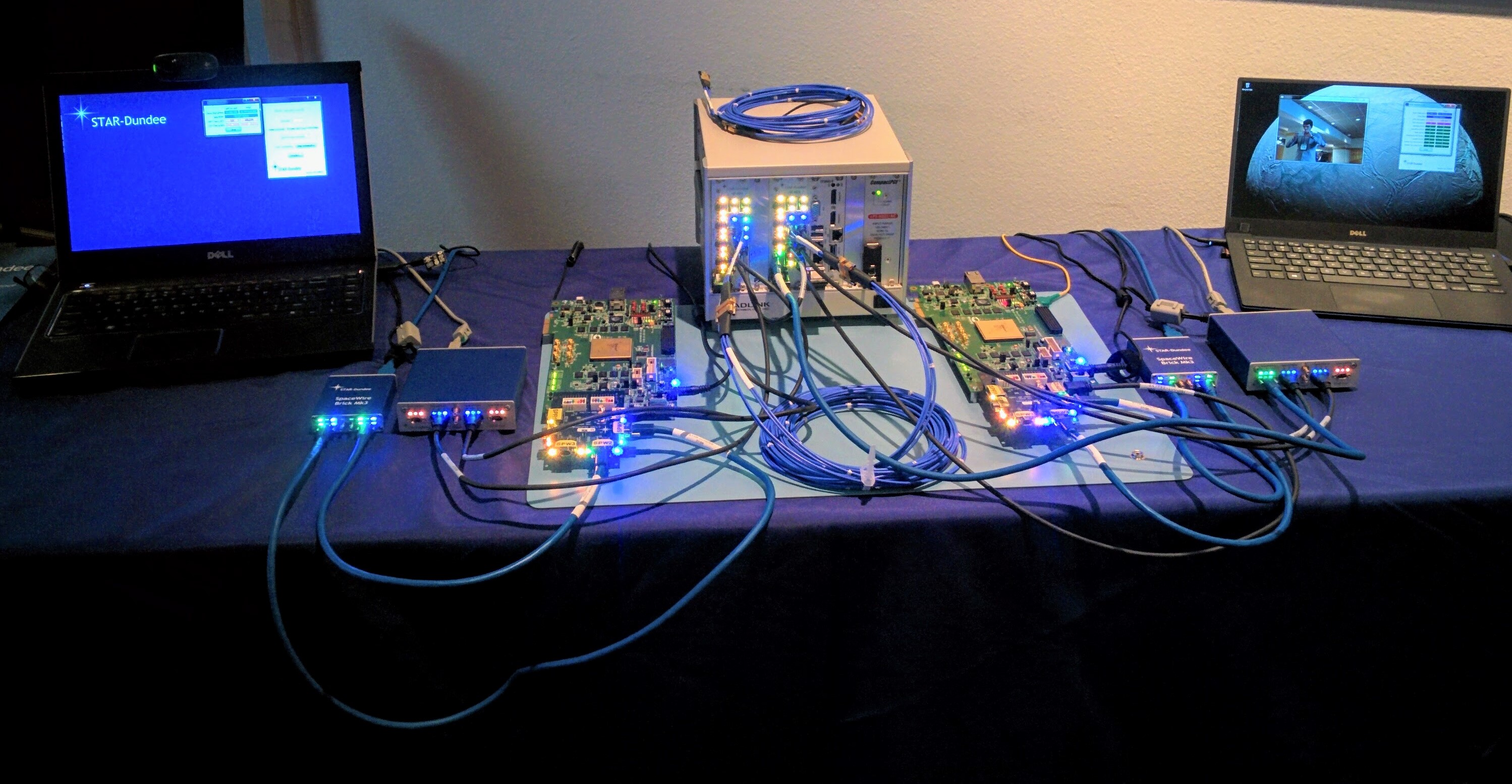
Figure 3 SpaceFibre Demonstration during operation
The demonstration system has shown the operation of SpaceFibre in a network architecture representative of a typical spaceflight on-board data-handling architecture. The SpaceFibre links were all operating at 2.5 Gbits/s. SpaceFibre was shown operating and interoperating on Xilinx Spartan 6 FPGAs and Microsemi radiation tolerant RTG4 FPGAs.