The SpaceFibre Network layer is responsible for transferring packets over a SpaceFibre link or network. The information to be sent is packaged in the same format as SpaceWire: <Destination Address> <Cargo> <End of Packet Marker>. It uses the same routing concepts as SpaceWire including both path and logical addressing.
The “Destination Address” is the first part of the packet to be sent and is a list of data characters that represents either the identity of the destination node or the path that the packet has to take through a SpaceFibre network to reach the destination node. In the case of a point-to-point link directly between two nodes (no routers in between) the destination address is not necessary.
The “Cargo” is the data to be transferred from source to destination. Any number of data bytes can be transferred in the cargo of a SpaceFibre packet.
The “End of Packet Marker” (EOP) is used to indicate the end of a packet. The data character following an EOP is the start of the next packet. There is no limit on the size of a SpaceFibre packet.
SpaceFibre Virtual Networks
A SpaceFibre network is effectively a set of independent parallel SpaceWire networks. These parallel, independent networks are called “SpaceFibre virtual networks”. Each virtual network runs over its own, distinct set of SpaceFibre virtual channels, comprising a virtual channel across each link used by the virtual network. Several virtual networks can then operate concurrently over a single physical SpaceFibre network. The overall physical network and the collection of virtual networks that run over that physical network is called the “SpaceFibre network”.
The traffic running over each virtual network is constrained by the SpaceFibre quality of service mechanism to remain within its allocated bandwidth and to observe the priority and schedule allocated to it. A virtual network is able to opportunistically use more bandwidth than it has been allocated, when no other virtual network has traffic to send over the links of the SpaceFibre network that the particular virtual network wants to use.
As far as the addressing of packets and their routing across the network is concerned, SpaceFibre operates in the same way as SpaceWire. This has the substantial advantage that existing application software or SpaceWire equipment can be used with a SpaceFibre network by simply tying a SpaceWire link interface to a SpaceFibre virtual channel interface. The application does not need to know that it is running over SpaceFibre, but gains all the QoS and FDIR advantages of SpaceFibre. This make the integration of existing SpaceWire equipment both simple and advantageous.
Packet Addressing
SpaceFibre uses both path and logical addressing, which operate in the same way as SpaceWire. It is not possible to route a packet between two different virtual networks in a routing switch. As already stated virtual networks on a SpaceFibre network are like a set of parallel, independent SpaceWire networks. The packet routing is within one virtual network.
Path addressing uses the leading data character of a packet to determine how the packet should be routed at the next routing switch. If the value of the leading data character is in the range 0 to 31, it determines which port of the routing switch the packet will be forwarded through. For example, if the leading data character is 2, the packet will be forwarded through port 2 of the routing switch. If the leading data character is 0, it will be routed to port 0, the internal configuration port of the routing switch. If the leading data character is 31 and there are only 9 ports in the router, the packet will be discarded. Note that the ports of a router are numbered consecutively, starting at 0 for the internal configuration port.
If the leading data character is in the range 32-255, it is a logical address. The value of the leading data character is then used as the index into a routing table, which once configured, determines which port the packet is to be forwarded through. For example, if the leading data character is 40 and the entry in the routing table for index 40 contains the value 3, the packet will be routed to port 3 of the router. The routing table is configured using RMAP commands sent to the router configuration port. Before configuration of the routing table has been done, any logical address will result in the packet being discarded. Path addressing operates at all times, before and after the routing table has been configured.
SpaceFibre Routing Switch
An example SpaceFibre router is illustrated in Figure 1.
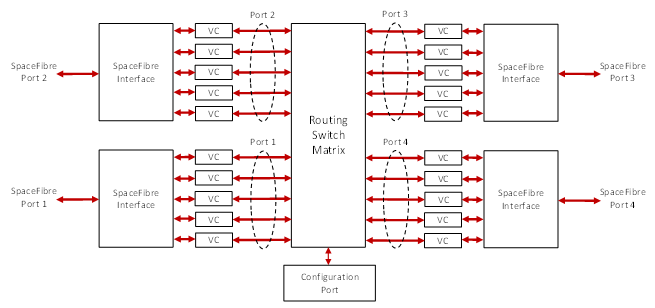
Figure 1 SpaceFibre Router
The SpaceFibre Routing Switch (commonly referred to as ‘Router’) supports Virtual Networks that behave like independent SpaceWire networks working at multi-gigabit rates. It also allows to bridge between SpaceWire ports and SpaceFibre Virtual Channels, providing QoS to SpaceWire networks.
Figure 2 shows an example of how the control network and two instrument data flows are assigned to VNs in four ports of a Router. Each SpaceFibre link implements multiple VCs, each one with specific QoS parameters. For example, the bandwidth allocation parameter of each VC can be set to the expected bandwidth of each instrument, so they do not interfere with one another or with the control network. VNs are built from the interconnection between VCs of different ports. These operate like SpaceWire networks.
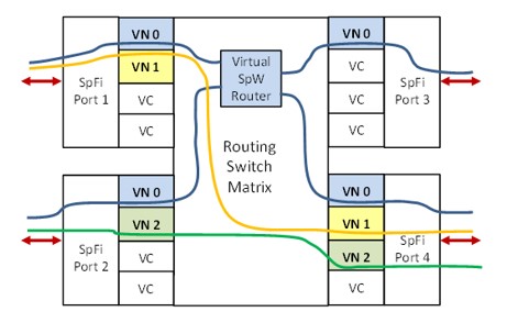
Figure 2 Simple SpaceFibre Network
Figure 3 shows a more realistic on-board network using SpaceFibre. Two high data-rate instruments (Instruments 1 and 2) have SpaceFibre connections, but for less demanding instruments it is possible to use SpaceWire connections connected over a SpaceWire to SpaceFibre Bridge. Each instrument has a virtual point-to-point connection to the Mass Memory Unit (VN 2 and VN 3) and there is a virtual point-to-point connection between the Mass Memory and the Downlink Telemetry Unit (VN 4). The Control Processor has a virtual network for configuring and controlling all devices on the network (VN 1) and the network itself (VN 0). Finally, a point-to-point connection between Instrument 2 and the Downlink Telemetry Unit also exists (VN 63). This architecture is solving a complex communication task with many separate, isolated virtual channels providing point-to-point links, and a virtual network being used to control the entire system. Figure 4 shows this same network with the virtual channels removed, revealing the simplicity of implementation of a complex communication task when using SpaceFibre.
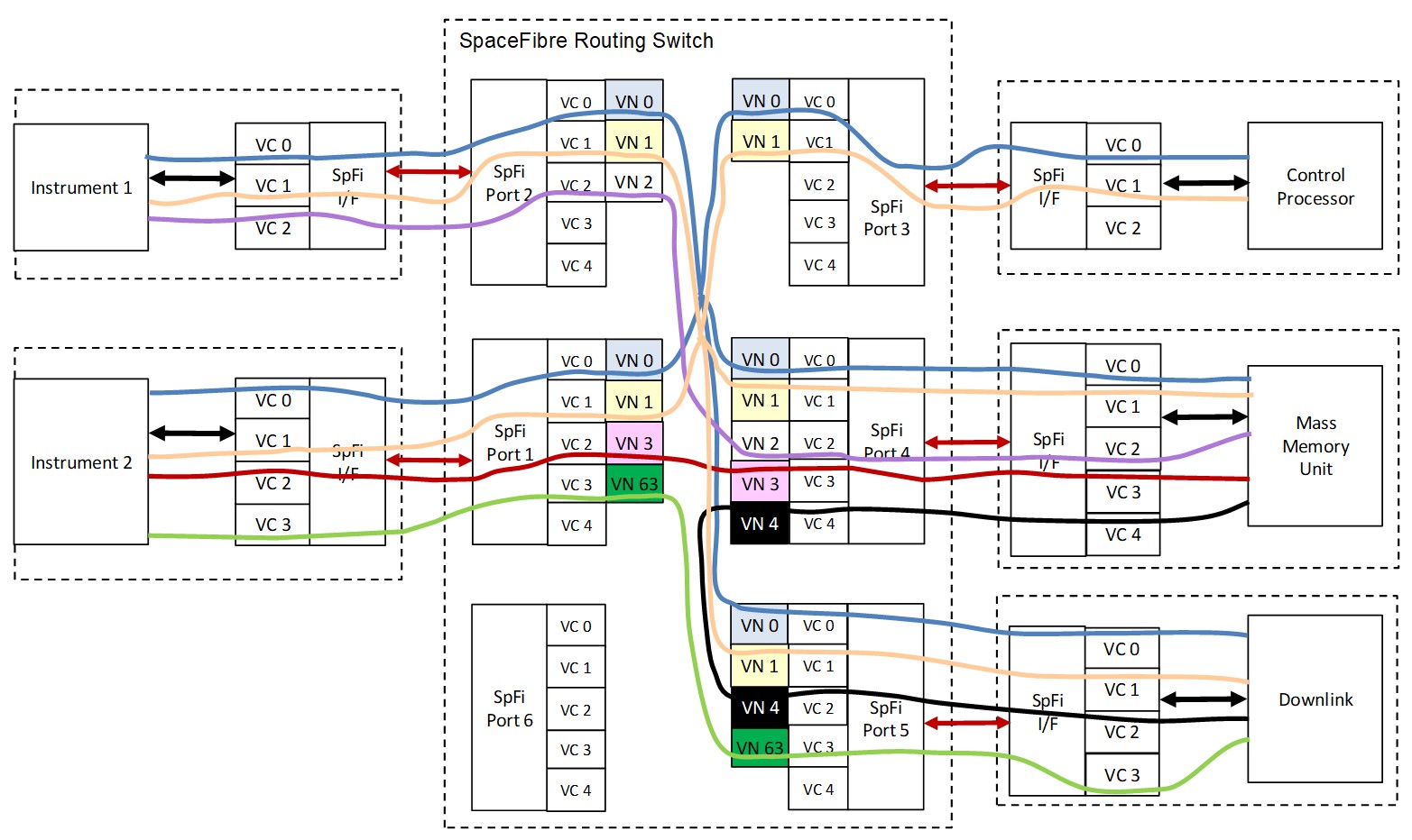
Figure 3 Realistic SpaceFibre Network
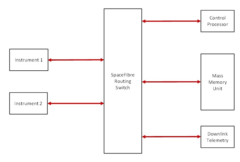
Figure 4 Simple System Architecture with SpaceFibre
Register to receive the SpaceFibre User’s Guide as soon as it is published.