Header deletion is the removal of the first data character of a packet after it has been used to perform its routing function. Header deletion is always employed in a router for path addressing, once a path address has been used it is no longer needed and is discarded, exposing the next path address character to be used by the next router encountered on the network.
Header deletion is not normally applied to logical addresses as the logical address gives the identity of the destination node. The one logical address character is by each router encountered by the packet as an index into the routers routing table, so that the router can forward the packet towards its intended destination. This does limit the number of nodes to 223, which is considered plenty for most spacecraft applications.
There is, however, a means of extending the number of logical addresses. Regional logical addressing uses a logical address in one region of a network, but if a packet crosses the boundary of one region into another region, its leading logical address is deleted, exposing another logical address character that is used in the next region. This is illustrated in Figure 58.
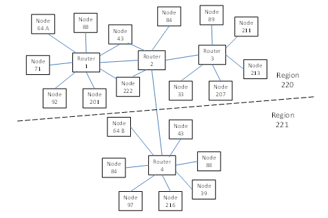
Figure 56 Regional Logical Addressing
Figure 56 shows a large network. Above the dashed line all the node logical addresses are unique, but below the dashed line some of the logical addresses are repeats of those above the line. Node 71 wants to send one packet to node 64 above the line (node 64 A) and another packet to node 64 (node 64 B) below the line. How can this be done? If the routers above the line are configured to route to node 64 A, a packet sent from node 71 with destination address 64 will end up at node 64 A.
To reach node 64 B the network is split into two regions: above the line and below the line. In each region the node logical address must all be unique. Each region is then given a logical address, which should not be assigned to any of the nodes. The region above the line is given logical address 220 and that below is given 221. Now to route from node 71 to node 64 B, the packet is given two cascaded logical addresses, the first of which is the logical address of the destination region (where the target node lies) and the second of which is the logical address of the destination node in that region. So for node 64 B this is 221, 64. The packet sent is then:
221, 64, cargo, EOP
The routers in region 220 are all configured to route any packet with logical address 221 first to router 2 and then on to router 4. Router 2 is programmed so that when the packet is forwarded from router 2 to router 4, its leading address character is stripped off, revealing the second address character:
64, cargo, EOP
The routers in region 221 are configured to route packets with logical address 64 to the local node with that logical address, i.e. to node 64 B.
To use regional logical addressing it is necessary to:
- Split the network into regions which are each given a logical address
- Within a region nodes must have unique logical addresses
- Nodes in two different regions can have the same logical address
- When routing a packet from one region to another the router must strip off the leading destination address character. This has to be specifically configured in the router.
- It is possible to cross regions to reach a destination, provided there is one logical address for each region.
For most spacecraft applications regional logical addressing is not necessary as there is normally far fewer than 223 nodes.