A routing table within the router is used to translate from the destination address at the front of a packet to the port number through which the packet will be sent. The router addresses are assigned as shown in Table 1.
| Address Range | Function |
| 0 | Internal Configuration Port |
| 1-31 (01-1F hex) | Physical Output Ports |
| 32-254 (20-FE hex) | Logical Addresses, which are mapped on to the physical output ports. |
| 255 (FF hex) | Reserved |
Table 1 Router Addresses
The internal configuration port is used to access configuration and status information of the router. A SpaceWire packet arriving at any port of the router with a leading destination address value of 0 will be routed to the configuration port. Configuration information that can be accessed via the configuration port includes the routing table, enabling the routing information to be programmed over the SpaceWire network. All SpaceWire routers have a configuration port. Since the configuration port is both the source and destination of SpaceWire packets that makes the configuration and status circuitry of a router a node.
The physical output ports are the actual SpaceWire ports on the router. For connecting to equipment local to the router it is not always necessary to use a SpaceWire link. In this case, a FIFO port can be used instead. The FIFO port is bi-directional and behaves like a SpaceWire port as far as the router, but there is no SpaceWire link attached to it. Instead, some user application connects directly to the FIFO port. The physical output ports of a router include both the SpaceWire ports and the FIFO ports. The physical output ports are always numbered from one upwards and normally the SpaceWire ports are first. So a router with four SpaceWire ports and two FIFO ports would number the SpaceWire ports 1 to 4 and the FIFO ports 5 and 6. FIFO ports are also called external or parallel ports, meaning external to the SpaceWire network, and parallel as opposed to the serial SpaceWire link. A router is allowed to have a maximum of 31 physical ports, hence the physical output ports are numbered 1 to 31 maximum.
Logical addresses are mapped by the routing table to physical output ports. It is necessary to be able to distinguish between path and logical addresses so that the router can handle them appropriately. This is done in a simple way: the value of the leading address character of a packet determines whether it is a path or logical address, if it is in the range 0 to 31 it is a path address, if it is in the range 32 to 255 it is a logical address. A path address is used directly to determine the output port that the packet is to be forwarded through. A logical address is used as an index into the routing table from which the physical port number is determined. The packet is then forwarded through the specific output port.
Logical address 255 is reserved for future applications and should not be used.
An example routing table for a router with four SpaceWire ports and the configuration port is illustrated in Figure 53. A ‘1’ in the table maps an address to an output port number. The configuration port (port 0) is accessed only via path addressing with the address 0. Ports 1 to 4 are accessed using path addresses 1 to 4 respectively. Path addresses beyond address 4 have no meaning in a 4-port router and give rise to a routing error. Logical addresses can be used to access any of the four output ports depending on how the routing table is programmed. For example in Figure 53, logical address 33 has been programmed to port 4. Any packets arriving with address 33 will be routed to output port 4.
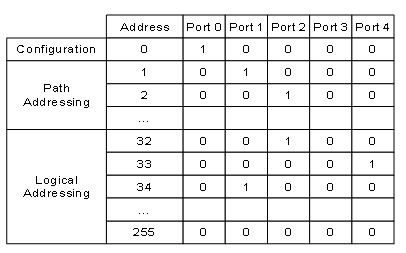
Figure 53 Routing Table for 4-Port Router