SpaceWire is able to support many different payload processing architectures using point-to-point links and SpaceWire routing switches. The data-handling architecture can be constructed to suit the requirements of a specific mission, rather than having to force the application onto a restricted bus or network with restricted topology.
An example SpaceWire architecture is shown in Figure 1. It uses two SpaceWire routers to provide the interconnectivity between instruments, memory and processing modules.
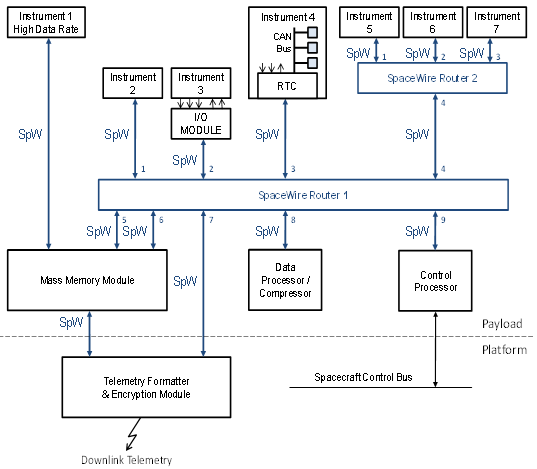
Figure 1 Example SpaceWire Architecture
Instrument 1 in the top left-hand corner is a high data-rate instrument. A SpaceWire point-to-point link is used to stream data from this instrument directly into the Mass Memory Module. If a single SpaceWire link is insufficient to handle the data-rate from this instrument then two or more links may be used in parallel.
Instrument 2 is of lower data-rate than instrument 1. Its data is passed though SpaceWire Router 1 to the Mass Memory Module.
Instrument 3 does not have a SpaceWire interface so an input/output (I/O) module is used to connect the instrument to the SpaceWire router. Its data may then be sent over the SpaceWire network to the Mass Memory Module.
Instrument 4 is a complex instrument containing a number of sub-modules which are interconnected using the CAN bus. A Remote Terminal Controller (RTC) is used to bridge between the CAN bus and SpaceWire. Other signals from the instrument are also connected to the RTC, which contains a processor for performing the bridging and local instrument control functions.
Instruments 5, 6 and 7 are located in a remote part of the spacecraft. To avoid having three SpaceWire cables running to this remote location a second router (SpaceWire Router 2) is used to concentrate the information from these three instruments and send it over a single SpaceWire link to Router 1 and then on to the Mass Memory Module.
This Mass Memory Module can receive data from any of the instruments either directly, as is the case for Instrument 1, or indirectly via Router 1. Data stored in the Mass Memory Module can be sent to the Telemetry Formatter/Encryption Module for sending to Earth, or it may first be sent to a Data Processing or Data Compression Unit. This unit may return the processed/compressed data to the Mass Memory Module or send it straight to the Telemetry Module via Router 1.
The Control Processor is responsible for controlling all the Instruments, Mass Memory Module and Telemetry unit. Via the SpaceWire Network it has access to all these modules: it can configure, control and read housekeeping and status information from them. The Control Processor is also attached to the spacecraft control bus over which it can receive telecommands and forward housekeeping information.
With several instruments and the Data Processor/Compressor sending data to the Mass Memory Module via Router 1, a single link from that Router to the Mass Memory Module may be insufficient to handle all the data, so a second link has been added to provide more bandwidth. In a SpaceWire network links can be added to provide additional bandwidth or to add fault tolerance to the system. In Figure 1 no redundancy has been included for clarity. In a spaceflight application, an addition pair of routers would be included with duplicate links to the modules to provide redundancy. It is straightforward to support traditional cross-strapped, redundant modules using SpaceWire.