The destination address at the front of a SpaceWire packet is used to route the packet through a network from the source node to the destination. There are two forms of addressing used in SpaceWire networks: path addressing and logical addressing.
Path addressing can best be understood using the simple analogy of providing directions to someone driving a car. To reach the destination you might suggest that the driver takes exit 2 at the first roundabout, exit 1 at the next roundabout, and finally exit 3 on the third roundabout. The driver will then have reached the required destination (see Figure 3). There is a direction to follow at each roundabout (take a particular exit). Together these directions describe the path from the initial position to the required destination. There is a list of directions to follow one for each roundabout. Once a direction has been followed it is crossed off the list and the next direction is followed at the next roundabout.
In a SpaceWire network the roundabouts are routers and the roads connecting the roundabouts are the links connecting the routers (see Figure 3). The list of directions is attached to the front of the SpaceWire packet forming the destination address. The first direction is followed when the first router is encountered. This direction is simply a data character that specifies which port of the router the packet should be forwarded through. A router can have a maximum of 31 external ports (port numbers 1 to 31) and one internal configuration port (port number 0). The leading data character at the front of the packet is used to specify the port that the packet is to be forwarded through: if the leading data character is 3, the packet will be forwarded out port 3 of the router. Once the leading data character has been used to forward a packet, it is discarded as it is no longer needed. This reveals the next data character in the path address for routing the packet at the next router. Figure 3, shows how the path address at the start of the packet is modified as the packet goes through the network. Since a router can have a maximum of 31 ports along with an internal configuration port, each data character forming a path address is in the range 0 to 31.
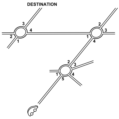
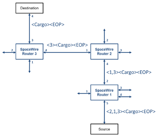
Figure 3 Path Addressing
Logical addressing can also be understood using the analogy of giving directions to a car driver. Logical addressing is like saying to the driver, “follow the signs to Dundee at each of the roundabouts”. This, of course, requires appropriate signs to be placed at each roundabout and each destination has to have a name or identifier so that it can be recognised on the signs. The logical address analogy is illustrated in Figure 4.
In a SpaceWire network using logical addressing, each destination is given an identifier, which is a number in the range 32 to 255. Each router in the network has a routing table (like the sign at a roundabout) which specifies what port the packet should be forwarded through for each possible destination identifier. The leading data character of a packet is set to the required destination identifier (e.g. 44 for Dundee). At each router the leading data character is used to look up the appropriate directions from the routing table and the packet is forwarded accordingly. For logical addressing the leading data character is not discarded at each router, since it will be needed to look up the path to follow at the next router encountered. The use of logical addressing is illustrated in Figure 4. Logical addressing uses just a single data character to identify the destination which is in the range 32 to 255 so that it does not get confused with path addresses.
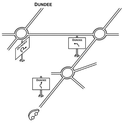
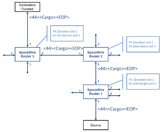
Figure 4 Logical Addressing
Logical addressing has the advantage that only a single address byte is required, but it does require the routing tables to be configured before it can be used. Path addressing requires a byte for each router and does not need routing tables in the routers.